
Introduction
You may have heard of auto-tune or even a talk box. The vocoder is a unique effect but all three have some way of manipulating a human voice with some other audio source - often giving the voice a robotic-like character.
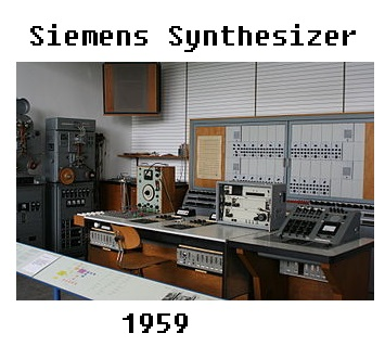
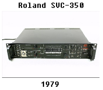
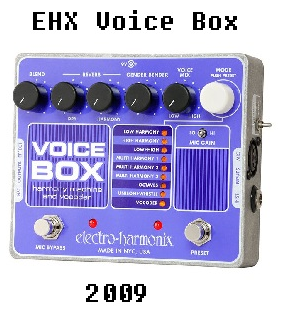
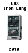
Figure 1: Four different vocoders from four different decades.
As you can see from Figure 1, the vocoder has been around for some time. It originated in the 1930s as a way to compress a speech signal for transmission. Eventually, the military began using this process as a way of encrypting messages that only someone with the right “decoder” could interpret. The Siemens Synthesizer (Figure 1 - left) is among the first vocoder systems intended for musical applications. Clearly this was not a portable device - when the SVC-350 came along, however, the vocoder could finally hit the streets. As we entered into the digital age these units became smaller until you reach EHX’s Iron Lung (Figure 1 - far right) which is roughly 3” x 6”.
How does a vocoder work?
What makes the vocoder a special effect is the way it processes signals; two signals enter, one signal leaves. There is a program signal, commonly the human voice, that is used to control a carrier signal, commonly some type of pitched instrument. On the vocoder output, you get pitch of the carrier signal with the envelope shape of the program signal. It often is used to sound like a voice is coming out of a guitar or keyboard (Daft Punk's "Harder Better Faster Stronger" is one of the iconic examples of vocoder use).

Figure 2: High level block-diagram for a generic vocoder [1].
Figure 2 shows the basic, “abstract”, diagram of a vocoder. Both input signals are processed by a suite of band-pass filters that isolate the midrange from the bass region, etc. Each vocoder uses The SVC-350 has 11 (analog) while the Iron Lung has 256 (digital). Each band-pass filter outputs to its own dedicated envelope follower.

Figure 3: Wikipedia’s presentation of the envelope of a sine wave [2].
“The envelope function of an oscillating signal is a smooth curve outlining its extremes." (Johnson, "Envelope (waves)").
The modulation stage uses the envelope of the program signal to control the passage of carrier signal onto the mixer stage. The way I like to think of the vocoder working is by imagining the voice signal’s envelope opening a gate for the instrument signal to pass through. As you play a guitar riff and speak at the same time, the output guitar riff will ebb and flow as you m
ake inflections and form words with your mouth. The mixer stage combines the individual frequency bands into one signal (the SVC-350 has a level control for each band, think 'eq'). The signal is then sent to a compression/gain stage for driving a speaker or guitar amplifier.
Objective
The goal of this design was to replicate the Roland SVC-350 11-Channel Vocoder. This completely analog vocoder has stood the test of time and remains as one of the sought after vintage models in the Vocoder-class of effects. With a recent rebirth of vocoder use in popular music (namely, Daft Punk among other successful artists), this seemed like a relevant exercise for the MetaMorphosys tool. The project was made possible in large part due to the manufacturer’s service manual for this piece of equipment. The service manual included:
- A (near) complete schematic of the vocoder
- A list of component part numbers
- A footprint image of the PCB
- Testing & verification procedures
The task of replicating the SVC-350 comes down to 6 major steps:Choosing components
- Modifications/Filling in schematic “gaps”
- Verifying design
- Constructing PCB layouts
- Optimizing Cost
- Assembling Design
Choosing Components
The first challenge was to survey the schematic and list of components that were used in the original design (circa-1979) and locate readily-available modern day components with similar behavior. Luckily, a few of those older components are still produced today. All it takes is just one vintage component that is too difficult/too rare to acquire to throw off the feasibility of this project; which brings us to the BA662A. I knew that there would be some modern-day equivalent to replace any old vintage electronic chip that would function the same. However, as I came across the BA662A it seemed that it behaved in such a way to produce a very desirable sound compared to similar devices. After scanning a few discussions on online forums, acquiring this chip seemed important.
Vintage chip: BA662
The BA662 is a voltage-controlled amplifier (VCA) that was included in the design of many Roland synths back in the day. It is also at the core of SVC-350 where the program signal is used to control the gate/envelope of the carrier frequency. These go for ~$40 on ebay and are no longer produced. Sure, I could have used the BA6110 as a replacement (a popular choice among vintage tinkerers). However, even this chip isn’t available from a large scale manufacturer which adds time and coordination to the manufacturing process. The process we use at MetaMorph involves sending gerber files to a PCB manufacturing house (Macrofab) where the board will be built and components will be placed; a one-stop-shop if you will. Luckily, the people at open music labs have reverse-engineered the BA662 to provide a transistor level equivalent. With their schematic and board files, I was able to model the NPN’s and PNP’s and wire them up accordingly - resulting in a fully SPICE configurable, ready to manufacture clone of the BA662 (We’ll get to SPICE later).
![Figure 4: BA662A Transistor-level equivalent as shown in the MetaMorph desktop tool [4].](https://images.squarespace-cdn.com/content/v1/548083a7e4b0d1770a9e3972/1446847840128-2HOT058RXO2B56MDB9IC/image-asset.png)
Figure 4: BA662A Transistor-level equivalent as shown in the MetaMorph desktop tool [4].
Figure 4 shows the cloned BA662A as viewed in our software tool. All of the blocks labeled 'Q_' are the dual transistor ICs as specified by open music labs. There are also a couple resistors in the design. The gray blocks labeled 1-9 correspond to the pins of the original BA662A, so when using this circuit block in a design it can be connected, pin-by-pin, just as the BA662A would be connected.

Table 1: List of parts showing original to modern equivalents.
Table 1 shows a list of components that were used in place of some of the original SVC-350 parts. The basis for most of these decisions came down to finding a transistor or diode with similar parameters to the original. In most cases the typical diode or transistor was sufficient. The voltage regulator was just a matter of finding a modern day converter for generating a bipolar +/-15VDC supply. I found an old datasheet for the uPC177C that made a reference along the lines of “the original version of this component is a 339”. This was a no-brainer once I realized TI makes a quad-comparator(LM339) with similar operating voltages. As you can see from Table 1, the LM139 comparator was used (not the 339) due to having a wider operating temperature range to the similarly functioning LM339.
Modifications/Filling in schematic “gaps”
The reason it was stated that I was provided with a near complete schematic is that there are a few sections that have 'blurred-out' components. Obviously, the service manual was intended for service and repair, not recreation of the equipment as a whole.
Filter Creation
For instance, the filter section contains 10 MFB Bandpass filters all tuned for a specific frequency. As you can see in Figure 2, the design of the filter is shown in the first channel. However, the values for resistance and capacitance have been left out.

Figure 5: Analyzer filter stage showing block diagram (left) and schematic (right) [3].
Luckily, they show the resonant frequencies of each filter in the block diagram with that information in conjunction with knowing the structure of each filter (copies of the channel 1 filter), I was able to use an online tool to set the right components.

Figure 6: Frequency response of 10-channel analyzer filter in SPICE.
As shown in Figure 6, the frequency analysis capability of SPICE was used to verify that all the filters were resonating at the correct frequency, with comparable amplitudes and shapes (‘Q’ value in engineering terms) to each other.
Omission of the Ensemble Effect
The SVC-350 has an integrated chorus effect (Roland calls it “ensemble”) that adds depth to the sound. Oddly enough, this is the part of the schematic Roland did not wish to disclose, labelling only a few ICs and leaving most of it blank, and evidently this section was not included. I could have inserted an arbitrary stereo chorus effect into the signal chain but in the end decided against it for two reasons. 1) It would be more time and money spent on just a bonus feature that 2) Could be easily added to a signal chain by an external, third-party chorus effect unit.
On the whole, omitting this section meant simply meant doing “less” (it also allowed me to omit the “analog delay” section which was just a side-car to the ensemble effect). There was a minor amount of circuit analysis, in which I had to make sure to hard-wire the circuit in a way so that the ensemble control was kept off and allowed the dry signal to pass through to the output.
Power Supply
The original SVC-350 is powered by a standard electrical outlet (120VACRMS) which is then transformed to about 18VACRMS. With the reliable third-party transformers being so common, I decided to power the board using a 18VACRMS wall-wart and not have to worry about getting zapped by high voltage.
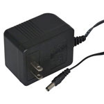
Figure 7: Common wall-wart style transformer [5].
Once I realized the entire system is being powered with +/-15VDC or less, it was easy enough to find a AC-to-Bipolar DC supply circuit provided by Texas Instruments’ LM337 and LM317 voltage regulator chips.
SPICE - Verifying Design
Overview
If you’ve never heard of SPICE-it is an electrical circuit simulation software capable of generating voltage and current waveforms that you can even listen to as an audio file. The last part of that description proved to be major player in the validation process. However, in order to generate an end-to-end SPICE simulation, each component in the circuit must have a defined SPICE model. Basic resistors and capacitors are simple, often . However, a specific op-amp or transistor might have some unique properties that need to be fully characterized for that component to be an accurate part of the signal chain. Here is a model for a TL082 dual op-amp, provided by Texas Instruments:

Figure 8: Single TL081 Opamp Spice model. Provided by Texas Instruments.
As you can see, the SPICE file for the op-amp is quite intricate. With dozens of high density SPICE models throughout the system, simulation time could and would approach 24 hours. To take some of the pressure of the CPU, the system was simulated in sections. Once a waveform is captured (in a .wav file format) it can be listened to and used as an input into a subsequent SPICE simulation. This provided a way to prove the circuit, block-by-block. I knew that the output of the compressor for each signal should sound louder and fuller than the input (there was usually gain in these compressors). When a signal generated didn't look or sound quite right, which happened often, it was useful to be able to sift through and pinpoint where the signal was being corrupted - this was usually due to a user error where I'd forget to ground an entire net of signals, etc.
SPICE has difficulty when trying to analyze large, bulky circuits - this process mitigates any hang ups SPICE might have about a circuit being too large. It should be noted that Figure 10 is just a general idea of the SPICE process. As you'll see in the next section, practically each circuit block was isolated and simulated with its own test inputs.
Potentiometer Adjusting
The service manual includes a section on adjusting the inner potentiometers (i.e. the kind you need a screwdriver for that aren't even seen unless you open up the hardware). As I intend to have matching potentiometers in the replica, I too went through and adjusted potentiometers according to the service manual.
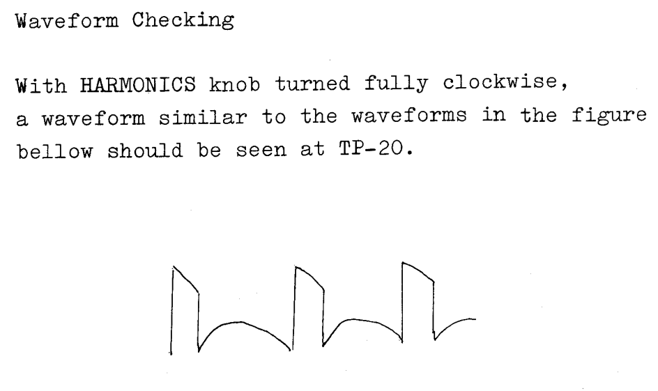
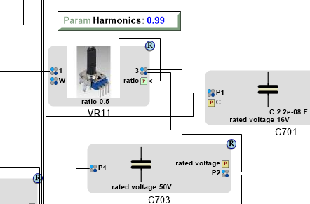
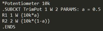
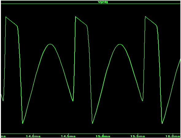
Figure 9: From left-to-right: 1) Service Manual Excerpt; 2) GME Potentiometer Setting; 3) Potentiometer SPICE Model; 4) Output waveform.
As shown in Figure 9 (Service Manual Excerpt), by maxing out the harmonics knob you should see a waveform of that specific shape. The GME Potentiometer Setting simply inputs a variable in the SPICE model (the GME variable will override the SPICE one). The output waveform (Figure 9 - far right) reasonably matches the one specified in the service manual. The effect is, of course, audible:
[insert audio sample of guitar signal with full harmonics compared to original].
The remainder of the potentiometer 'adjusting' followed the same process as the harmonics section.
Vocoding
This is the penultimate step: An end-to-end SPICE simulation with actual guitar and vocal audio-clips being used as inputs.

Figure 10: High level block diagram of SVC-350 Vocoder showing SPICE 'sections'.
It turned out that the section labeled 'SPICE B' had a very long simulation time due to the carrier and formant signals being combined at 11 separate channels.
Even though, SPICE is just a simulation tool, being only an approximation of the real world, the benefit can be monumental when you are about to spend hundreds or thousands of dollars on getting something manufactured. The process of transcribing a circuit of this complexity can be pretty daunting so being able to verify that all the connections are in the right place before sending it off for manufacturing can save large amounts of time and money. Fortunately, all of the components (omitting switches and jacks) came with a well-defined SPICE model.
Constructing PCB Layout
The original SVC-350 is a dual-rack mount (18” x 14” x 4”) and the version of eagle we have in-house allows for a maximum board size of about 6” x 4”. I aimed for a 3 board solution:
A board for the external connections (instrument/mic inputs, amplifier outputs, power supply). This also contains the conditioning sections for inputs and outputs (pre-amps, compressors, and output gain stage circuits).
A board for the vocoder process. This is the where the carrier signal gets combined with the program signal, in other words this is where the guitar signal gets “vocoded” by the microphone signal. This board contains the filters and signal detectors for the two inputs. It also contains the compander (compressor + expander) that acts on the vocoded signal.
A board for the control interface. This will contain all the potentiometers that are found on the face of the original SVC-350 (11-channel EQ, mic level, harmonics, output level, balance).
Optimizing Cost (In Progress)
The estimated cost for the 3 circuit boards along with the components to populate them came out to ~$1200. I can buy an actual SVC-350 on ebay for $1200 right now. Clearly, there’s some optimization to be done. It turns out, a significant part of the cost is the labor charge from the PCB manufacturer for placing the components on the board.

Table 2: Quantity of components in design.
The PCB manufacturer carries certain select house components with guaranteed stock that incur almost no labor cost. Replacing as many of the components we have with their house components will be the first step.
Assembling Design
While the majority of SVC-350 components were placed on one large circuit board, the replica design consists of three smaller circuit boards (due to prototyping considerations). Large terminal blocks consisting of up to 36 terminals (3 rows of 12) will be included to consolidate the interconnection of signals between boards.

Figure 11: Physical layout of terminal block with index labeling.
Each of the three boards will have a section similar to the one shown in Figure 11. 16AWG wire will be soldered directly to each of the vias (green circles in Figure X) at the correct location.

Table 3: Indices of connections to terminal blocks.
In an effort to keep the board-to-board connections organized, Table 3 was made to show the position of each signal on each board’s signal bank. For instance, the interconnection for the “Filter Input” signal between the bottom and middle board are at index 1-7 and 3-7 on their respective signal banks.

Figure 12: Board layouts of the three circuit boards that make up the vocoder system, with terminal blocks highlighted.
As seen in Figure 12, the terminal blocks act as a portal for the signals The input and output jacks along with power conditioners and preamps were placed on on the bottom board. The front panel holds all of the knobs and faders used for adjusting levels. The middle board contains the 'meat' of the vocoder (i.e. all of the filters and envelope analyzers).
Conclusion
Overall, this project was very enlightening. Having started with little knowledge of vocoders, I learned a lot from studying the circuit. I learned that the program signal (voice) acts as somewhat of a volume-control for the carrier signal (i.e. instrument). Also, through the verification process - I learned how SPICE can be an interactive tool that lets you not only see the output but to hear it as well (a powerful verification method for audio circuits).
References
1) "What Is a Vocoder?" Linux // What Is a Vocoder. 9 July 2015. Web. 13 Oct. 2015. <http://www.sirlab.de/linux/descr_vocoder.html>.
2) "Envelope (waves)." Wikipedia. Wikimedia Foundation, 21 Sept. 2015. Web. 13 Oct. 2015. <https://en.wikipedia.org/wiki/Envelope_(waves)>.
3) SVC-350 Service Notes. 1st ed. Roland, 1983. All. Print.
4) "BA662 Clone." BA662. Open Music Labs, 3 Apr. 2014. Web. 13 Oct. 2015. <http://wiki.openmusiclabs.com/wiki/BA662>.
5) "Jameco Electronics." ADU180100: JAMECO RELIAPRO: Power Supplies & Wall Adapters. Web. 13 Oct. 2015. <http://www.jameco.com/webapp/wcs/stores/servlet/Product_10001_10001_121216_-1>.